 |
 |
RC Tanks Australia ForumRemote Controlled Tanks Australia
|
|
It is currently Tue Apr 16, 2024 8:06 pm
All times are UTC + 10 hours
 
|
Page 1 of 1
|
[ 2 posts ] |
|
| Author |
Message |
|
Phyrephish
|
Post subject: Upgrading a HL Pz. III to Full S&S With IR Capability  Posted: Posted: Mon May 23, 2011 4:54 pm |
|
Joined: Tue May 10, 2011 1:17 pm
Posts: 1123
|
|
Upgrading a HL Pz. III to Full S&S With IR Capability and Metal Track & Gears
« on: December 20, 2009, 03:48:20 AM » - Repost from the old Hobby Havoc Site
With the release of Heng Long’s RX-18 control board infrared battle capability for Heng Long tanks became easily affordable upgrade option. The RX-18’s easy plug configuration makes any such upgrade appear at first glance to be quite straight forward. However, the process of upgrading tanks to full IR capability isn’t quite as simple as it should be and the lack of documentation only make the process more challenging for the first timer. With this in mind I though a comprehensive upgrade guide could be beneficial to many tankers. Consequently, I have tried to document here a complete upgrade process for a NON smoke & sound Heng Long Panzer III to a full smoke & sound tank with metal gears and IR battle capability. The airsoft gun will be consigned to the bin and a more realistic scale barrel will be used.
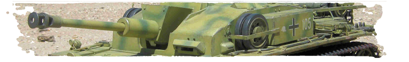
Anyone who upgrades a tank is unlikely to stop at just an upgrade of the internal electrics without any corrections or modifications to the exterior of the tank. Once the upgrade to IR capability has been completed the second part of this guide will look at some corrections and modifications of a stock Heng Long Pz III. This project will turn the bog standard grey Heng Long Pz III pictured below…
into…..THIS …a Panzer III Ausf. L of the Pz. Abt 502 Leningrad, 1942
PART ONE FULL RX-18 UPGRADE with METAL GEARBOX
There are two sections to Part One, one section devoted to the hull and the other to the turret or more specifically the main gun. Each section can be worked on first but to work on the turret first you will need to complete Steps 1 and 2 of Section 1 which deal with separating the top deck and turret from the lower hull.
Section 1. HULL BASIC
Step 1. Separate the hull from the top deck & turret
Turn the tank over and remove the seven screws holding the top deck & turret.
Step 2. Disconnect 8-Pin & Aerial connectors
To fully separate the two halves of the tank disconnect both the 8-pin & aerial connectors. If you wish to work on the turret first then you can now jump to Section 2.
Step 3. Remove Control Board, Motors & On/Off Switch
Each motor and gearbox assembly is secured to the hull with 3 screws. Remove all of these screws. The motors driveshafts are also connected to the drive sprockets so the screws attaching these will also have to be removed and the drive sprockets gently pulled off the shafts. This can be done without removing the tracks. Once the drive sprockets have been detached remove the RHS motor by pulling the motor up and forward (rotating about the driveshaft) to free the gearbox from the positioning pins underneath. Repeat for the LHS motor.
The control board is secured by three screws, one easily located in the middle of the hull, the upper screw is slightly obscured by the tracks and the bottom screw is located near the suspension arms. None of these screws are particularly hard to get to and the board can be removed with out any disassembly of the suspension system. Underneath the control board is the on/off switch. Remove the small mounting screws holding the switch in place. Finally cut the wires from the battery to the switch as close to the switch as possible. All the internal components can now be removed from the hull.
Step 4. Replace Motors
If your new motors with metal gearboxes do not have the 2-pin wire connectors already attached you will need to do so yourself.
For each motor the BLACK wire connects to the tab nearest the 3 openings in the motor case. The RED wire should connect to the solder tab closest to the single opening in the motor case. (The OPPOSITE as shown below)
Installation of the motors is best done as a reverse of how they were removed. Starting with the left had side motor at about 45° to the hull insert the drive shaft then rotate the motor down onto the positioning pins. Fix in place with the three screws and repeat for the right hand side motor.
Once the motors are in place the drive sprockets can be re-attached to the drive shafts. As stated before the whole process of gearbox replacement can be done without removing the tracks or any of the road wheels
Step 5. Rewire On/Off Switch
The power switch for most Heng Long tanks is actually double pole switch. If you cut the wires from the switch, fire up your soldering iron and remove all the excess solder you will probably find that you have 6 contacts on the switch rather than 3. If so connect the wires from your battery to the middle pair of contacts. Connect a 2-pin connector to a pair of outer contacts. This 2-pin connector will supply the power to the RX-18 board.
(NOTE: Kamaz has suggested an alternate means of re-wiring this switch in his post )
Step 6. Insert Receiver Board & Speaker
Unsolder or cut the aerial connecting wire from the old control board and solder into position as shown below on your new TK-YL101 receiver board. For added strength add a bit of hot glue around the base of the wire. Insert a receiver crystal, connect a 3-pin wire connector and secure the receiver board in place with 3 screws. Place the Heng Long speaker into position towards the left rear of the hull and secure in place with the three screws used to mount the old control board.
Step 7. Wire the Volume Control
The wiring of the volume control is one of the two issues that cause the most concern in an upgrade to the RX-18 board. If you are upgrading an existing smoke & sound tank then you will already have a suitable volume potentiometer. However it will need to be re-wired. The easiest way to do this is to buy an additional 3 pin - 3 pin bridge cable. Cut off one of the connectors and solder the three wires to the back of the volume control board as per the figure below.
In this particular case a NON- smoke & sound unit is being upgraded so a new volume control is needed. The volume control itself is simply a 10k trimpot. Most trimpots have a pretty standard pin out arrangement. The green wire goes to pin 1, yellow to pin 2 and the blue wire to pin 3 (see below)
(Note: I happened to have a spare Heng Long Volume control board and have used it for the first stages of this upgrade project.)
Step 8. Secure Volume Control & On/Off Switch
For this stage secure the switch and volume control in position on the hull floor. Eventually the on/off switch and volume control will be moved to a more accessible location. Make flush the four protruding squares on the top of the battery compartment.
Step 9. Attach the RX-18 and Associated Wires
Cut 2 x 5 mm lengths of double sided foam tape place on the underside of the RX unit and mount as shown. If you plan to keep the airsoft unit then you cannot mount the RX unit in this location. It will need to be mounted on the side where the old control board was located.
Step 10. Install the Smoke Unit and Attach Wires
The Heng Long smoke unit attaches to the rear of the hull and is secured again by three screws through the bottom of the hull. Now is as good a time as any to start connecting all the wires to the RX-18 board.
Step 11. Wire Smoke Unit On/Off Switch
A switch must now be wired in to turn on and off the smoke unit. Any simple switch will do but to save costs I reuse the Heng Long switch that turns on or off the airsoft gun. Removal of this switch is covered in Section 2 Turret Basic.
Step 12. Construct Internal Aerial & Mount Smoke Unit Switch
At this point a decision should be made as whether to keep the supplied aerial or install an internal one. If you plan to keep the original one then there is no need to change the original aerial connector. If you want to install an internal aerial then there are a few ways to do it. The first thing you will need is some wire, in particular enamel copper wire which is suitable for winding chokes, crossover coils etc. This wire has an enamel coating which acts as an insulator (something that needs to be remembered when soldering). I have chosen to use 0.63mm (22swg) wire from Jaycar Electronics (WW4018). It comes in a 36 m roll at about $10. Expensive for a single aerial yes but only 331 mm is needed per aerial. One roll can produce over 100 aerials (true cost 10 cents each). Once you have cut 331 mm of wire it can then be wrapped around a short length of plastic/styrene tubing which is then placed inside the hull. Many users have had no problems with this type of aerial. However, I have. had much better results by bending the wire into an S-shape for Panzer IIIs & IVs or a U-shape for Tigers and hot gluing across the rear of the hull. In the case of the Panzer III I drill a series of holes in the rear hull attachment and thread the wire through into the shape of an S (see below). I then snip off the other half of the old aerial connector wire connected to the old aerial and solder this to the new aerial. (NOTE: Even though it doesn’t look like the aerial wire is insulated. Remove a few mms of insulation with some sandpaper or file BEFORE attempting to solder.)
The rear hull attachment also provides a great space to locate the smoke unit switch. Cut a 22 x15 mm piece of styrene (at least 3 mm thick) and in turn cut an opening for your switch.
Step 13 TEST
The tank is now ready for the first test of your RX-18 installation. Make sure that you have a new smoke & sound transmitter unit and that it is fitted with a matching transmitter crystal. Turn on the transmitter, turn on the tank, rotate the volume control to half way and press the start button on the transmitter. If all goes well you should hear the engine start up sound. If not maybe the on/off switch is back to front, flick to the other position and try startup again. If the tank runs backwards instead of forwards then your left and right motors are connected to the RX-18 the wrong way around, simply swap them over. Make sure to test the smoke unit switch as well.
OH YEAH ..... I FORGOT
If you are upgrading from a NON smoke & sound unit then you will need to get a new transmitter and a pair of matching crystals before you will be able to test your installation. The RX crystal pops into the two big holes on your TK-YL101 board and the TX crystal into the front of your new transmitter.
COMING UP NEXT SECTION 2. THE TURRET ....
_________________
rctanksaustralia.com
|
|
  |
|
|
|
Phyrephish
|
Post subject: Re: Upgrading a HL Pz. III to Full S&S With IR Capability Posted: Mon May 23, 2011 5:22 pm |
|
Joined: Tue May 10, 2011 1:17 pm
Posts: 1123
|
|
Section 2. Turret Basic
Step 1. Identify the Gun Motor Return
Connect an 8 Pin wire connector from your control board to connector on the underside of the top deck. Make sure that you have an aerial connected. Turn the tank on and startup with the transmitter. Using a multimeter verify which wires and attachments on the small PCB connector control the gun motor. Place the red probe on the middle red wire solder pad and the black probe on either of the black wire pad. Set the multimeter to read voltage. Push up the left joystick. If you have the black probe on the wire and pad that is connected to the gun motor about 5 volts will show on the multimeter display as the left joystick is pushed up. TAKE NOTE OF THIS WIRE. 9 times out of 10 it is the black wire towards the outside of the tank.
Step 2. Remove Turret
Once you have marked which black wire supplies the gun motor snip all three wires from the little square PCB and unscrew it. Remove the two turret screws to free the turret rotation ring and the turret itself. At this stage there is no need to remove either the turret motor or 8-Pin connector.
Step 2. Add 3 Pin Connector
In order to make assembly and disassembly easier in the future the PCB above that serves only as a connector is replaced by a proper 3-Pin connector. It is probably best to keep the wiring consistent with the red wire in the middle and the black gun motor wire on the outside. This type of connector is cheap and readily available locally from Jaycar electronics. A second 3 pin connector of this type can be used to mount the IR receiver and the 2 pin versions can be used for connecting LEDs.
Step 3. Disassemble Turret and Remove Airsoft Gun
There are 5 screws holding the turret together, 4 around the turret ring and one to the rear of the stowage box. Remove them all and the turret will come apart. There is another screw holding the front part of the turret and airsoft unit in place. Remove this screw to completely free the airsoft unit, mantlet and gun barrel. Cut the wires going to the warning LED and to the On/Off switch for the gun. Remove the warning LED and the switch which can be reused as the switch for the smoke unit (see Section 1, Step 11). A largish spring is situated between the turret roof and the airsoft unit which may pop out with the gun. Make sure to keep it. Finally, separate the barrel and mantlet from the airsoft unit.
Step 4. Disassemble and modify Airsoft Gun
Ok here is where you have to make a decision. Do you want to buy an aftermarket gun recoil/elevation unit and keep your airsoft gun in tact OR chop up your airsoft unit for a cheap and easy way to keep your gun elevation with the possibility of adding the aftermarket recoil later. I’ve chosen the latter.
Once you have removed the airsoft unit unscrew the front cap part as this can be used later. This front cap is always cracked so if it splits in two don’t worry because if you need it later it will have to be split in two in any case. Open up the main part of the unit and remove the motor and gears. After you have removed all of the insides reassemble the unit and cut along the red dashed line in the picture below so that your unit will look like that on the right.
Since we will be reusing the original Heng Long Gun barrel for the moment insert the short section of black (or pink) tube from the front of the airsoft gun back into position. This will provide an attachment for the gun barrel.
Reassemble the airsoft unit including the front cap so that the unit looks like the picture below.
Step 5. Connect Elevation and Gun Motor Wires to 3-Pin Connector
With the modified airsoft unit complete reassemble the turret assembly. Solder the leads from the gun elevation motor to the male half of the three pin connector that was used in Step 2. Take care to solder the black elevator motor wire to the correct pin on the connector. Cut a 10 cm length of red wire and another colour of your choice. These two wires will be your gun motor wires which will in fact connect up to the coil of a relay switch. The red wire connects to the middle pin of the 3 pin connector and the other wire to the remaining pin as per the picture below. I have chosen to terminate the gun motor wires in yet another 2 pin connector. To save on costs/time & effort you may wish to leave off the connector and solder these wires direct to the coil of your relay switch (next step)
Step 6. Wire Turret 8-Pin Connector
Ok this step is the most important step and the one that causes the most grief in the upgrading to the Heng Long IR system. When you purchase an IR upgrade make sure that you do get all the parts required. Most retailers now have available complete kits. Make sure that your kit has an additional 8-Pin connector for the turret.
Using the diagrams below as a guide the solder pads on the underneath of the 8 –pin connector are as follows from LEFT to RIGHT.
1. Red IR LED (‘+’ve)
2. Black IR LED (GND)
3. Blue IR Detector (GND)
4. Yellow IR Detector (Sig)
5. Brown IR Detector/Flash LED (‘+’ve)
6. NC
7. White Flash/Cannon Sound/Track Recoil Trigger
8. Orange (GND)
For the system to function correctly there needs to be some form of switch that completes the gun trigger circuit by connecting the #7 pad to the ‘-‘ ve (GND) #8 pad. It is this switch that confuses most people that attempt to upgrade earlier Heng Long tanks to IR capability. On the Heng Long models that come from the factory with the IR system installed this switch is a small microswitch located on the recoil unit. In the case of stock Heng Long tanks this mircoswitch provides a dual function not only does it close to complete the circuit and trigger the gun flash, cannon sound and track recoil but it also provides the momentary flash required for the standard flash LED. The aftermarket Asiatam recoil system for the RX-18 features two microswitches, one for this purpose and the other to control the barrel recoil.
From here things can be either really simple or a little bit more complicated. If you do not intend to get a recoil unit and are happy to use the standard Heng Long BB barrel and purchase a High Voltage flash all that you need do is connect a diode in line between the #7 pad and the gun motor return wire (which is in fact the ‘-‘ve (GND) pole). In this case when you push up the left stick the gun motor circuit is ‘turned on’ and functions as a switch allowing the white wire at pad 7 to connect to GND via the diode.
If you wish to use a high voltage flash and Asiatam recoil system there is a second microswitch on the Asiatam unit that controls the flash and is pre-wired to simply plug into the RX-18. However, this switch turns on when the barrel fully recoils, thus, the flash and cannon sound will actually occur after the gun has fired. .If this is not a problem for you then the simple wiring above will be all that you will need and even the diode can be omitted.
If you wish to use a modified Heng Long recoil unit or an Asiatam recoil unit and a scale barrel then you can wire the connections as shown below for the most realistic gun simulation. Note this involves significant re-wiring of the Heng Long or Asiatam recoil units but will result in gun flash and sound FIRST followed immediately by the recoil of the barrel. Note: The second microswitch with the connections to the RX-18 board on the Asiatam unit can be removed.
Despite it’s looks the circuit above is both cheap and easy to assemble. I will cover how to make this circuit and some other electronics in my next section (Section 3. Electronics)
Step 7. Position IR LED
Positioning of the IR LED for a Pz III Ausf L. is the easiest for any of the Heng Long tanks. There are two openings in the add-on armour for the mantlet in which the IR LED can be inconspicuously placed shown below and marked A & B. The standard 5 mm Heng Long IR LED can be easily placed behind opening A. However, in this case I have chosen to trial a 3mm IR LED which will be placed in a 3mm hole drilled behind opening B.
(NOTE: I have since found that 3mm IR LED are not strong enough for IR Battle)
If you choose opening B for the placement of your IR LED then you will need to make a corresponding opening in the front of the turret for the wires.
Step 8. Position IR Receiver
One item that will more than likely be missing from your upgrade kit is a 3 pin connector for the IR receiver. Heng Long use the same connector as featured on their 3 pin cables so in a pinch you could cut one end off a 3 way cable and solder the wires to the underside of the 8-Pin turret connector. Here I have chosen to use a small 3 pin connector readily available from Jaycar. Wiring of the connector is very important. The blue (signal) wire should be placed on the side, the black (GND) wire in the middle and the supply voltage (red) on the other side. To maintain consistency with Heng Long I suggest hot gluing the connector to the turret roof as shown with the blue wire on the RIGHT HAND SIDE. This blue wire matches up to the smaller of the two pins on the IR receiver and you should always connect the IR receiver so that the small pin and blue wire are together.
Step 9. Reassemble Turret
Reassemble the turret, gun and mantlet. The turret 8 Pin connector can be hot glued inside the cavity of the old airsoft unit.
IMPORTANT: At this stage of the conversion I have not decided which recoil system to use and in the interim will be using a high voltage flash unit. Thus the photo below shows a version of the simplified wiring system with no additional Flash LED timer circuit.
Step 10. Install High Voltage Flash & Test
The main PCB of the Heng Long high voltage flash can be placed in either the turret or inside the Pz III hull. If it is placed in the hull you will need to ‘pull out’ the flash bulb from the barrel every time you wish to separate hull & turret. In this case I have mounted the PCB just in front of the RX-18 and hot glued the 2 pin wire connectors to the side of the RX-18 to keep them from interfering with turret rotation.
If everything is correct up to this point your tank is now capable of IR battle. Reassemble the entire tank, hull and turret and test. You will not be able to test the IR unless you have a second IR ready tank to battle with.
Next Up I'll cover the electronics in a bit more detail......
_________________
rctanksaustralia.com
|
|
| |
|
|
|
|
|
Page 1 of 1
|
[ 2 posts ] |
|
It is currently Tue Apr 16, 2024 8:06 pm
All times are UTC + 10 hours
Users browsing this forum: No registered users and 1 guest |
| |
|
|
You cannot post new topics in this forum
You cannot reply to topics in this forum
You cannot edit your posts in this forum
You cannot delete your posts in this forum
You cannot post attachments in this forum
|

|
|


